This is the long version. If you just want to know what the device is and whether you want one, read the SunVario introduction instead. What follows is the engineering: what the finished hardware measured on the bench, and what the numbers forced me to change.
What the device is
The SunVario is an audio variometer that runs on sunlight. There is no battery in it. A solar panel covers the whole top face, the energy goes into a 10 F lithium-ion capacitor, and that capacitor is the entire power system: no cell to age out, no charge controller deciding when to stop, no chemistry degrading while the device sits full in a hot cockpit.
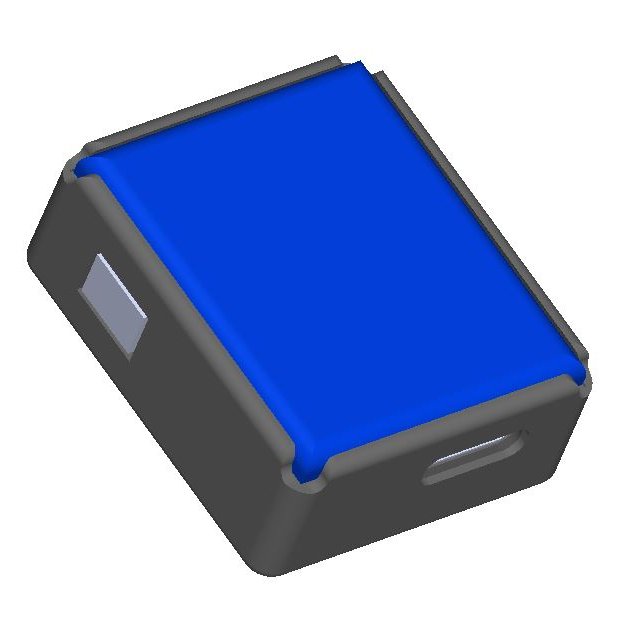
The interesting part is the scale it fits into. The finished device is 29 × 34 × 12.1 mm and weighs 9.8 g — panel, capacitor, buzzer, USB-C, radio and enclosure included.
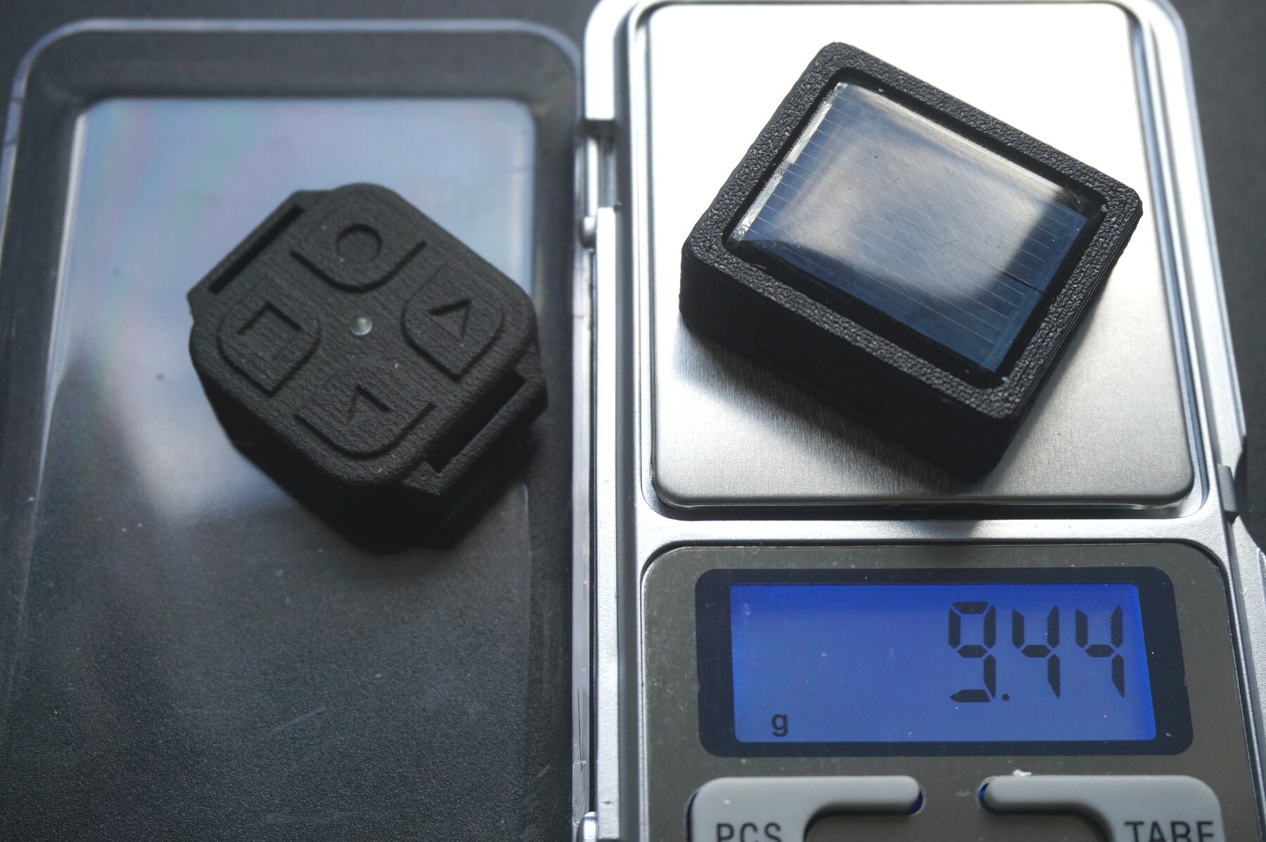
That is the whole product on the scale, printed body and all — this particular unit came in at 9.44 g. That is the size of a matchbox and the weight of a couple of coins. I have not found another solar vario anywhere near it; the ones that exist are the size of a phone, because a lithium cell and its charge management take room and a capacitor does not.
Inside: an nRF52832, an SPL07-003 barometer polled 62 times a second, a PAM8904E charge pump driving a 12 mm piezo, USB-C, and Bluetooth LE that publishes pressure at 10 Hz as a standard characteristic, so any flight app takes it as an external sensor. One button turns it on, cycles three volume levels and turns it off. Everything else is configured from the browser.
Designing around a capacitor instead of a battery moves every hard question into one place: the energy budget. There is very little energy on board and it has to be spent well. Which is what the rest of this article is about.
Why measure at all
For a long time that budget existed only on paper. Capacitance times voltage window, divided by an
assumed current, equals hours. In August 2026 I finally sat down with a finished unit — call sign
FBSV.BC42 — and measured it properly. Almost everything the arithmetic predicted was wrong in an
interesting direction.
The measurement trick: the bank is its own ammeter
You cannot put a multimeter in series with this device without changing what you are measuring. The consumption is in the tens of microamps, the buzzer draws in bursts, and the whole point is long unattended runs.
So I used the capacitor itself. Charge is Q = C·V, and with a fixed 10 F bank the current is
just I = C·dV/dt. I read the voltage over BLE once every 15 minutes — connect for a few seconds,
read, disconnect — and let it run. Thirty-three points over eight hours, not one dropped
connection. What comes out is average current over each interval, which is exactly right here:
the instantaneous current is meaningless when a buzzer chirps in bursts.
The read itself costs something — a connection every 15 minutes plus 30 seconds of fast advertising after each disconnect works out to about 12 µA of parasitic load. I subtract it where it matters and say so.
Discovery 1: the current is not a constant
Here is the raw shape of an eight-hour discharge, vario on, volume 1, no phone connected:
| Window | Voltage | Slope | Mean current |
|---|---|---|---|
| 0–2 h | 3227 → 3116 mV | −55.4 mV/h | 154 µA |
| 2–4 h | 3116 → 3008 mV | −54.1 mV/h | 150 µA |
| 4–6 h | 3008 → 2912 mV | −47.9 mV/h | 133 µA |
| 6–8 h | 2912 → 2829 mV | −41.5 mV/h | 115 µA |
The device slows itself down as it drains. At the bottom of the window it eats a third less than at the top.
The reason is the buzzer. The piezo is driven by a PAM8904E charge pump, and the volume setting is the multiplier — the amplitude on the piezo is a multiple of the input voltage. A piezo is a capacitive load, so power scales with the square of the drive, and the drive follows the bank. As the bank sags, the beeps get cheaper.
Fitting 28 sliding windows over the 2.86–3.19 V range gives a clean power law:
I(V) = a · V^n a = 2.96 µA/V^n, n = 3.46 ± 0.55 (V in volts)Which integrates into a runtime formula — the time to fall from V₁ to V₂:
            C          ⎛    1          1    ⎞
  t = ───────────── · ⎜ ────────  −  ───────⎟
       a · (n − 1)     ⎝ V₂^(n−1)    V₁^(n−1)⎠
Checked against the measured run, 3.227 → 2.829 V: the formula says 8.16 h, the stopwatch said 8.00 h. Two percent. And the exponent barely matters — anything from n = 2.9 to n = 4.0 puts the total between 16.6 and 17.1 hours, because the curve is pinned to a measured segment.
The practical consequence is that a budget computed from the current at a full bank underestimates runtime by roughly half again. It also means the honest thing to show a pilot is hours remaining, not a percentage — the same formula gives it directly, and percentage of charge is a lie when the load itself depends on charge.
Discovery 2: the barometer costs more than the sound
This one I did not see coming. The device is an audio variometer; I assumed the piezo dominated everything.
Measured on one unit, no connection, everything else identical:
- barometer polling stopped: 56 µA
- barometer running: 197 µA
The SPL07-003 costs 141 µA all by itself. It gets polled every 16 ms — 62 times a second — and every one of those wakes the MCU. For comparison, the entire first volume level of the buzzer adds 106 µA, and a live BLE connection streaming pressure adds about 200 µA.
The most expensive background item in an audio vario is not the audio. It is the sensor that feeds it.
That turned into a firmware change rather than a hardware one. The sensor is only needed while
somebody is listening: either the vario is beeping (volume > 0) or a connected phone is subscribed
to the pressure characteristic. Everything else is polling into the void. So ess_start() /
ess_stop() are now driven by exactly that condition — and, importantly, from both paths.
Changing the volume from the app used to write the setting without touching the sensor, which
meant muting from the phone bought you no savings at all, and unmuting left the vario silent until
the next reboot. That is what the whole ess_sync_with_volume() shim exists for.
Discovery 3: sound gets cheaper than theory says
Three volume levels, measured under a vario simulator so the beep pattern is identical regardless
of weather (vario_simulator_value_cm_s = +100 cm/s), phone connected and subscribed at a steady
10.1 notifications per second:
| Volume | Measured | at V | Buzzer’s share | Normalised to 3.6 V | Exponent |
|---|---|---|---|---|---|
| 0 (silent) | 248 µA | 3698 mV | — | — | — |
| 1 (1×) | 354 µA | 3659 mV | 106 µA | 104 µA | k^1.00 |
| 2 (2×) | 503 µA | 3618 mV | 255 µA | 254 µA | k^1.28 |
| 3 (3×) | 735 µA | 3580 mV | 487 µA | 490 µA | k^1.41 |
Pure capacitive theory — P = f·C·(k·V)² — predicts 1 : 4 : 9. What actually happens is
1 : 2.4 : 4.7, roughly k^1.35. Charge-pump losses at the higher multipliers and a piezo that
stops behaving like an ideal capacitor near resonance both eat into it.
So the loudest setting costs about five times the sound energy of the quietest, not nine — and because the baseline is significant, only about double the total current. Turning the volume up is not the disaster the datasheet arithmetic suggests.
The numbers that matter
Working window is 3.8 → 2.7 V: the top is where the charge path clamps, the bottom is the hardware cutoff that protects the capacitor. That window holds 11 C = 3.1 mAh = 9.9 mWh — the entire energy budget every number below has to fit into.
The two ends behave differently in practice. Sun reaches the clamp: I have charged past 3.72 V on a windowsill. USB does not — the charge path runs out of headroom around 3.5 V, so a cable fills most of the window but not the last stretch of it.
Everything in the table below is computed from 3.6 V down, which is where the discharge logs start. Treat those hours as the conservative figure: a bank topped up by sun sits above that, and the extra 0.2 V is worth roughly another one and a half to two hours depending on the mode.
Runtime, integrating with the voltage dependence included:
| Mode | Current @3.6 V | Runtime |
|---|---|---|
| silent, no BLE, barometer stopped | 48 µA | 52 h |
| no BLE, barometer running, occasional beeps | ~154 µA @3.2 V | ~17 h |
| BLE + subscriptions, sound off | 248 µA | 10.1 h |
| BLE + subscriptions, volume 1, climbing 50 % of the time | 301 µA | 8.5 h |
| BLE + subscriptions, volume 2, climbing 50 % of the time | 375 µA | 7.0 h |
| BLE + subscriptions, volume 3, climbing 50 % of the time | 491 µA | 5.4 h |
| BLE + subscriptions, volume 3, climbing continuously | 738 µA | 3.7 h |
The “50 %” column is the realistic flight: half the time you are climbing and the thing is singing, half the time you are gliding and it is quiet.
A device nobody connects to, beeping occasionally, lives about 18.4 h from a full bank.
Charging: what the physics allows
Start from the bank, not from the charger. The whole working window is 11 coulombs; from the hardware cutoff at 2.7 V to the 3.8 V clamp, that is all the charge that exists in this device. So:
| Charge current available | Time to fill the whole window |
|---|---|
| 30 mA | 5 min |
| 100 mA | 90 s |
| 300 mA | 30 s |
Over USB the limit is not the bank, it is the charge path — which is also why a cable stops lifting the bank at about 3.5 V while sun carries it to the clamp. From a genuinely empty device the current sits at whatever that path allows and the voltage climbs linearly, because a constant current into a capacitor is a ramp. A minute of cable is enough to put a flying day back into it. What you cannot do is extrapolate from a stopwatch reading taken near the top of the window: up there the charger has left constant current and is regulating, the current decays exponentially, and the last few percent take longer than the first eighty. That is the region where naive measurements are made, and it is why I quote the calculated envelope rather than one of them.
Over solar I have a measured run. On the morning of 16 August, from 2896 mV to 3724 mV — a flat-empty bank to full — took 35 minutes, which works out to 3.9 mA average — morning light, with resin over the cells. Put that next to the consumption table above: the hungriest state this device has — volume 3, phone connected, climbing without a break — draws 738 µA. The panel brings in about five times what the device can spend. In sunlight it is not slowly losing ground, it is filling up while it works, and the capacitor only has to cover shadow, turns away from the sun, and the evening.
The panel does not connect straight to the capacitor. Its output goes through a boost harvester that runs the cell near its maximum-power point and lifts whatever it gets up into the bank, clamping at 3.8 V. That part exists because the cell is a low-voltage one: it cannot reach the capacitor’s window on its own. It is also the piece I most want to simplify — a boost stage, an inductor and an MPPT resistor network is a lot of board area for a device this size, and a panel whose maximum-power voltage already sits inside the capacitor’s 2.5–3.8 V window would let all of it go away. That is a hardware revision away, not a firmware setting.
A capacitor helps here in a way a battery does not. It needs no constant-current/constant-voltage profile, no charge termination, no coulomb counting. It needs exactly two things: don’t exceed the top of the window, don’t fall below the bottom. And at 60–80 nA of self-discharge it loses about 0.1 V in six months — which sets a hard rule for everything else on the rail: anything permanently connected to a 10 F bank has to stay well under a microamp, or it, not chemistry, becomes the thing that empties your device in storage.
What the enclosure turned into
The electronics settled; the enclosure did not. That order is normal and worth saying out loud: on devices this size the enclosure traditionally eats far more time than the electronics, and more than the firmware too. A board gets designed, fabricated and populated; a case gets designed, printed, held in a hand, found wanting, and designed again.
The parametric model that describes this little box is 1328 lines of OpenSCAD today, plus 558 lines of geometry checks that run on every build. Everything in it is fitted to tolerances where five hundredths of a millimetre are a real quantity — the difference between a cap that clicks and a cap that rattles, or between a lip that prints and a lip the slicer quietly drops.
The board is 20.32 × 26.8 mm, double-sided, with 3 mm of its length given over to the BLE antenna. The finished case is 29 × 34 × 12.1 mm — and the outline is set by the panel, not the board. The difference between the two is absorbed by the two walls opposite the button and the USB port, where there is empty cavity to give away.
The earlier design was a tray with one face plate: the plate trapped the panel’s edge and carried the button. On real printed parts that produced two defects. The relief slits for the button tongue surfaced on the top face, next to the panel, and looked terrible. Worse, the plate worked as a lever — pushing the panel with a thumb loaded its top edge, and the long side pressed the button, occasionally sticking it down. Both came from one part doing two jobs.
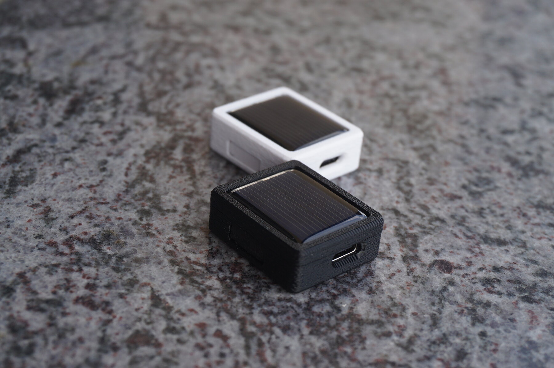 The first batch, printed in two colours. Layer lines are a first-batch artefact, not the design.
The current design splits it into three printed pieces:
- Tray — floor, board stops, USB window, capacitor pocket, tether eye, pusher window. On top of the wall: a recess for the cap, a shelf for the panel, and a 0.8 mm rim.
- Cap — a frame that goes on from the outside and clicks onto ribs running almost the full length of each side. It prints upside down, top face on the bed, so the lip over the panel is the first layer and there is nothing to bridge or support.
- Bar — the button, and nothing else. A thin flat plate lying against the right wall, held only at its ends by low ribs growing out of the front and rear walls. That makes it a beam on two supports with a ~25.7 mm span instead of a short cantilever: 2.6 N/mm, about 1.05 N to press. No relief slits needed at all. It never touches the panel — its top edge sits below the seam.
Two details took the most iterations. The panel seat: the panel measures 24.8 × 29.8 rather than the nominal 25 × 30, and only its 1.0 mm PCB substrate holds an accurate edge — above that it is poured resin with a meniscus. So the tray’s rim grips the substrate only, and the cap’s lip is a flat shelf landing on the resin’s shallow slope, which gives a line of contact that survives a panel being a little thicker or thinner. The first attempt, a wedge following the panel edge, ran at the same angle as the slope, so engagement degenerated into hundredths of a millimetre and the lip came out thinner than a print layer.
The cap fit: 0.15 mm clearance per side gave 0.3 mm of play, 0.08 still rattled. It is now zero — the skirt sits on the recess with no gap and the interference comes from printing itself (elephant foot on the first layer, perimeter spread). Snap ribs 27 and 22 mm long, 0.6 mm proud, sitting at the very bottom of the cap wall so the wall is the longest possible lever and the click is easy.
The cavity is a tuned Helmholtz resonator, and that is designed, not lucky. This is an audio instrument: the piezo is what the pilot actually experiences, so the box around it is treated as part of the acoustics rather than as packaging.
There are no internal partitions, so the whole interior is one chamber — from under the board to the gap beneath the panel. The model computes its volume zone by zone and subtracts everything solid: the ramps, the board, the capacitor, the piezo, the USB shell, and the leftover plastic of board stops, button strip, USB collar and tether eye. That comes to about 4295 mm³. From there it solves the Helmholtz relation backwards — given a target frequency, what port area does it need — and prints the answer for 800, 1000 and 1200 Hz on every build.
The port turned out to be somewhere you would not think to look. The slit around the button pusher is geometrically open, but acoustically it is a labyrinth with two turns: it adds resistance, damps the Q and sets no frequency. The USB shell sits tight in its opening. What actually vents the chamber are the four ~0.7 mm holes in that shell’s foot, where the connector is soldered to the board, with 0.3 mm of steel as the neck. Four identical holes work in parallel, so their areas add while the end correction still follows a single hole. That puts the resonance near 1092 Hz — inside the buzzer’s band, where the case reinforces the sound instead of muffling it.
Which is the point: the enclosure gives the piezo back loudness that a sealed box would have taken away, using holes that were going to be there anyway.
Where it stands
Firmware 0.24.0, barometer SPL07-003 on SPI, nRF52832, PAM8904E driving a KLJ-1230 piezo, LIC0813Q3R8106 as the bank, USB-C, solar panel across the top face. The device starts on a button press and only on a button press — a solar instrument that wakes up beeping in your pack is an anti-pattern, not a feature. It shuts down on a long press, and on the hardware cutoff at 2.7 V.
On temperature I would rather be conservative than clever: the design target is −5 °C and above, which covers about 95 % of real flying. It will very probably keep working below that — the limit is the capacitor’s behaviour in the cold, not the electronics — but colder days are exactly the days when the sun has to do more of the work, and I would rather have that verified than assumed.
The photo above is the first printed batch. Production units get a finer layer height so the print lines stop being part of the industrial design.
If you want one, it is on sale — and the introduction to the device is the shorter read.