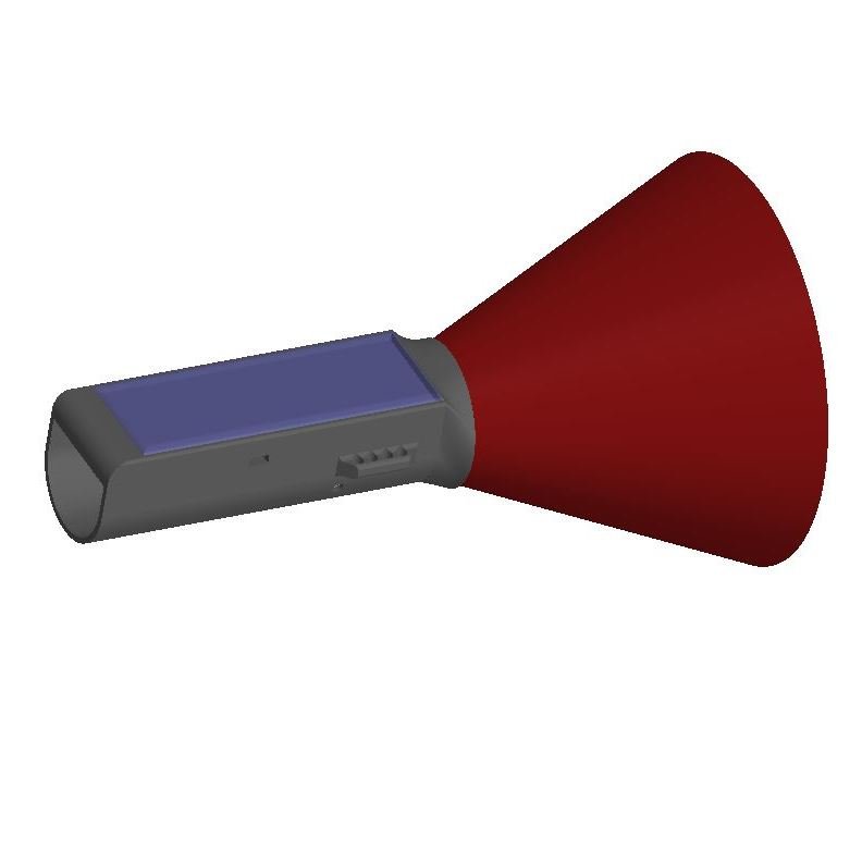
An external true-airspeed (TAS) sensor that exposes its data to flight apps over Bluetooth. Optimised for paraglider speeds, but usable on hang gliders up to about 103 km/h IAS.
Theory
The sensor uses a pitot tube as its primary measurement element. The relevant equations:
Where: — speed (m/s); — differential pressure (Pa); — static pressure (Pa); = 8.31447 J/(mol·K) — universal gas constant; — molar mass (kg/m³); — relative humidity (fraction); — saturated water-vapour pressure; — saturation temperature (K); — temperature (°C); = 133.3 — unit-conversion coefficient (for Pa).
Plugging in standard density = 1.225 kg/m³, you can get away with a differential-pressure sensor alone and obtain indicated airspeed (IAS). For true airspeed (TAS) the theory requires a static-pressure sensor, a temperature sensor and a humidity sensor.
Sensitivity analysis: at 50 km/h, a ±50% humidity change shifts the result by only 0.1 km/h. So humidity can be ignored. A 10 °C temperature change shifts the result by 1 km/h. A 10 kPa change in static pressure shifts it by 3 km/h. With a near-zero accuracy of the differential pressure sensor of 0.1 Pa, the minimum measurable speed is 1.5 km/h. The maximum measurable speed under standard atmosphere is 103 km/h, corresponding to the differential sensor’s upper bound of 500 Pa. Accuracy improves at higher speeds because the speed-vs-pressure relationship is quadratic.
The differential-pressure sensor has a fairly large scale tolerance of about 3% — different units can read up to 3% apart. That is 0.7 km/h at 50 km/h, but it is static, not stochastic. Scale repeatability is about 0.5%, meaning for a constant true pressure the reading wobbles by ±0.5% — that gives ±0.13 km/h at 50 km/h. Overall, all the error sources are acceptable.
Other formulations exist whose results match the above to within a small error, which gives some confidence in the derivation.
Simplified, with humidity fixed at 50%, the final formula becomes:
Or, ignoring humidity entirely (as in standard conditions, 0%):
The humidity-driven error is an order of magnitude smaller than the pitot tube’s inherent error, which is exactly why aviation traditionally ignores humidity.
The theoretical speed still has to be corrected for the instrument’s pitot-tube geometry via a calibration coefficient .
Pitot tube
Simulations showed that the internal tube diameter strongly influences the local loss coefficient, which rules out the small DIY tubes sold on mass-market platforms. Based on extensive simulation and parametric study, I designed a custom pitot tube. Its dimensions are much closer to those used on real aircraft than to typical hobby tubes. As speed rises, accuracy improves — up to a point. That is why the pitot tube’s geometry matters most at low speeds.
When speed increases, the pressure in the static chamber barely changes, while the dynamic-chamber pressure rises. That differential reaches the differential-pressure sensor placed directly behind the pitot tube. The tube is integral with the rigid-plastic body, so internal resistance is lower and accuracy higher. The resulting correction coefficient is 4%, compared with up to 50% for typical mass-market pitot tubes.
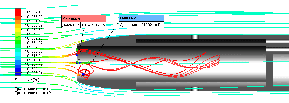 CFD pressure field around the custom pitot tube — the geometry that drives the 4% correction coefficient.
Electronics
The device is built on the Nordic nRF52 Bluetooth MCU with a hardware FPU, which makes the math fast. No modules — the whole circuit fits on a single PCB: differential pressure sensor, static pressure sensor with temperature, MCU, reset button, Li-ion charging connector, voltage regulator, solar-panel connector, BLE antenna.
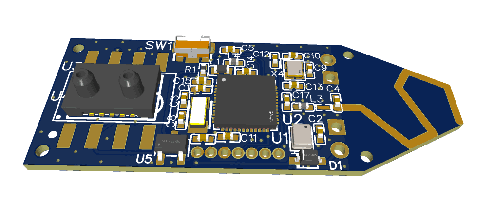 Single-board schematic: differential and static pressure sensors, MCU, charging, BLE antenna.
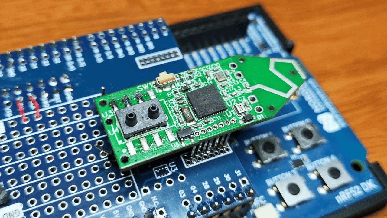 PCB v3 layout — 44 × 15 mm, the most technologically dense board in the FlyBeeper line.
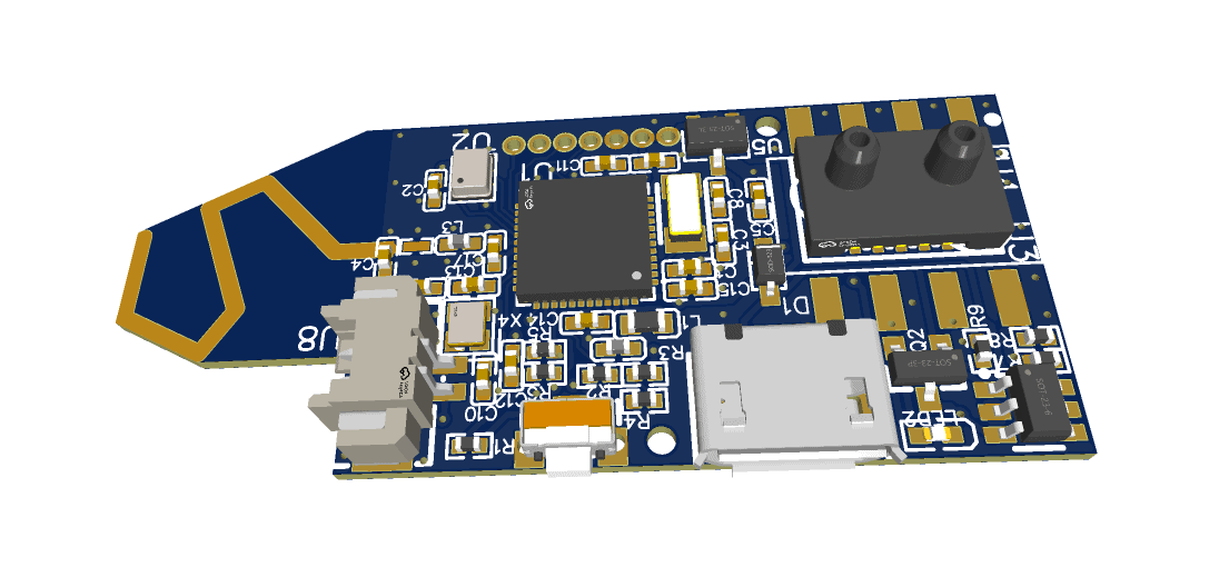 PCB v3 3D render fitting inside the transparent pitot body.
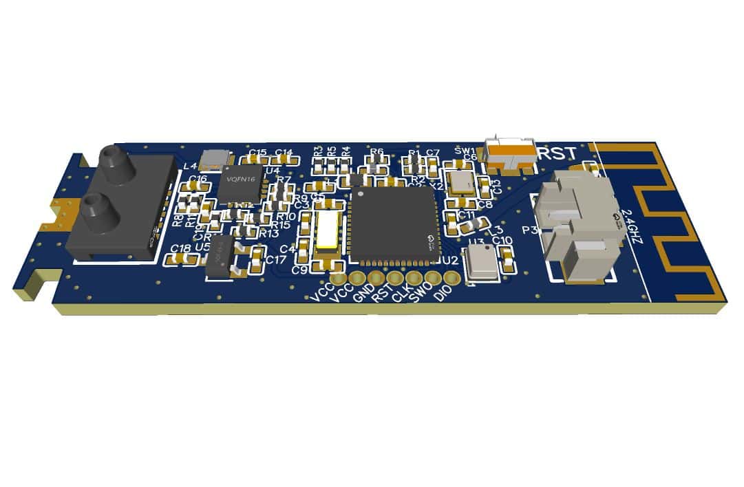 Assembled PCB v4 with USB Type-C charging and supercapacitor.
Version 2 was designed with USB Type-C charging. Version 3 brought solar back, but with a much smaller panel that required a sophisticated power management circuit. This is the most technologically dense board I have designed. It measures only 44 × 15 mm. The board together with its solar panel and battery fits entirely inside the transparent body of the pitot tube. There is no USB connector — the solar panel’s output is 3× the circuit’s average consumption, which means the circuit can run indefinitely even at 1% charge as long as there is light. Without sun, a fully charged battery lasts 40 hours.
Version 4 brought USB Type-C back for fast charging — in a couple of minutes — of a modern supercapacitor. Dropping the Li-ion cell extends the operating-temperature range to -15 °C to +65 °C with a much longer service life.
Bluetooth
Computed TAS is exposed via the 0x1819 Location and Navigation Service. The TAS characteristic is not standardised and probably never will be (rare use case), so I generated my own UUID: 234337bf-f931-4d2d-a13c-07e2f06a0249. For consistency with the Bluetooth spec, I populated the Characteristic Presentation Format so clients know the value is an INT16 LE, formatted to one decimal place, in km/h. IAS is also available separately at UUID 234337bf-f931-4d2d-a13c-07e2f06a0248, and EAS at 73741cd2-a392-427a-af70-6bdb5e0a715b.
Static pressure and temperature are exposed via Environmental Sensing notifications, the same as in the FlyBeeper Pressure Sensor and FlyBeeper mini BT. Battery percent is exposed via the standard 0x180F Battery Service, characteristic 0x2a19 Battery Level.
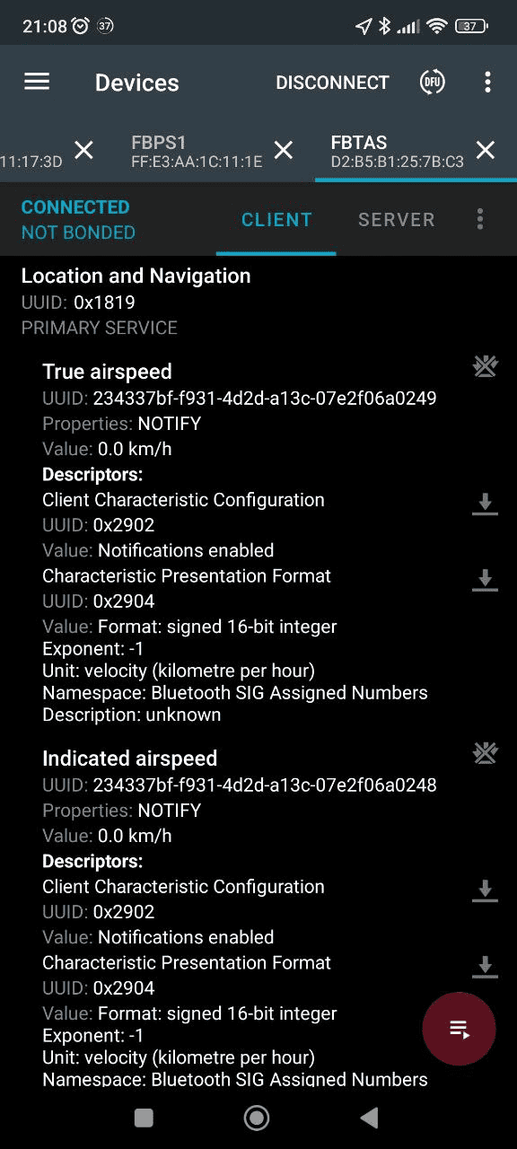 TAS characteristic in the Location and Navigation Service (nRF Connect, Russian UI).
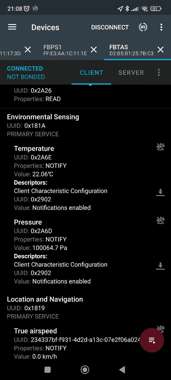 TAS notifications: INT16 LE, one decimal place, km/h (Russian UI).
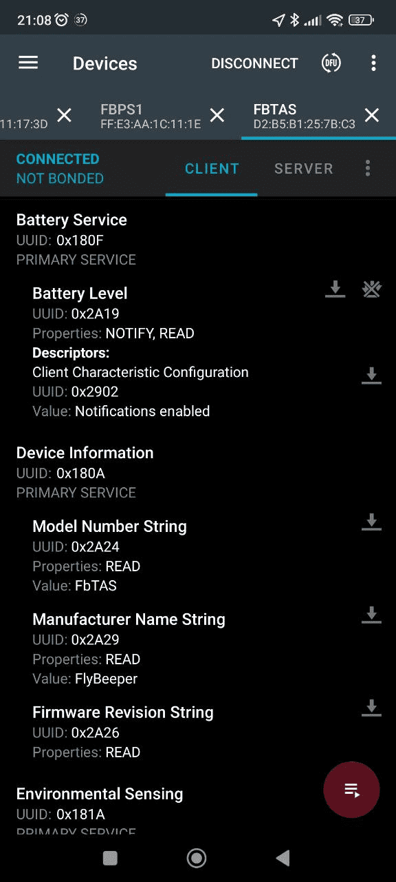 Static pressure and temperature on the standard ESS service (Russian UI).
Operating modes
The chip is so power-efficient that the device is always on. Without an active BLE connection, all sensors sleep and the MCU advertises every 4 seconds — enough to discover and connect to.
In this mode a fully charged battery lasts several years. When connected over BLE, subscribing to the temperature characteristic alone wakes only the temperature sensor; subscribing to the pressure characteristic wakes pressure and temperature; subscribing to the true-airspeed characteristic powers up all sensors.
There is also a technical mode for over-the-air (OTA) firmware updates. Implementing it is not hard, and it pays off: if any issues come up in the field, users get a simple update path.
Enclosure
The initial concept was a single rigid homogeneous-plastic body containing the pitot tube, the electronics compartment, an adjustable mount, and three tail-fin stabiliser blades. The design was driven by flow simulation and was to be refined after field tests. Priorities: rigidity sufficient to survive transport; low local-resistance coefficient for accuracy at low speeds; a tether storage system that uncoils reliably when the device is deployed; low weight (35 g) to limit pendulum effects.
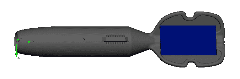 Initial single-piece body: pitot, electronics compartment, mount and three tail-fin stabilisers.
The first field tests revealed weak points around the inspection hatch. For version 2 the tail-mounted solar panel was temporarily dropped because the mount was not rigid enough. I redesigned around a 20 mm tube with 1–1.5 mm wall thickness as the main body. The tail stabiliser is now removable, which gives both repairability and the option to install the device on a hang-glider frame.
Version 3 looks similar to version 2 but uses a transparent polypropylene tube, which made it possible to install a tiny solar panel inside the body. However, high temperatures forced the panel back outside, and after flight testing the tail stabiliser was replaced by a badminton-style shuttlecock.
After more test flights, I moved the BLE antenna to the front to improve link quality, shortened the body to 6 cm and added Type-C for a few-minute recharge. In this configuration the body is hard to break, and the nylon shuttlecock tolerates very rough handling. The result is very compact — total length about 11 cm.
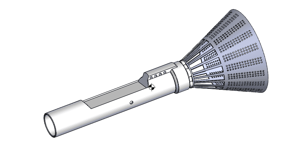 Final body with badminton-style shuttlecock tail — total length about 11 cm.
Software
As of September 2024, xcTrack, SeeYou Navigator and LK8000 read the TAS characteristic directly. An alternative text-packet output in LXWP0 format is also implemented, which makes the device compatible with most flight apps that consume BLE-tunneled UART data.
A companion progressive web app is available — installable, works offline. At a minimum it displays the data and logs changes. It is what I use for testing. Through it you can configure the device and update its firmware. Its only limitation is that it does not yet work in the background. On the upside, it has a dark mode for OLED screens and is translated into six languages.
For sensor calibration there is a separate utility based on swinging the sensor on a circle of known radius. Distance is traversed-circumference × turns; divide by time to get speed. Averaging requires several turns. The turn count must be large enough not to lose timing precision but small enough to avoid accumulating error in the radius measurement. The speed should not be so low that the sensor drops earthward and shrinks the effective radius, but not so high that you cannot get at least 3 samples per turn to average out air movement. Optimum: 10–15 seconds, 1.3–1.5 m radius, 30 km/h.